
As part of an ongoing investigation in to excess noise (also called 1/f noise) from resistors I recorded some data taken with the AP515 and posting it here. All 3 tracks have 80 dB of gain added to them using Audacity. The actual signal level from the resistor is a few microvolts. The part being tested is a Yageo RC0603FR-072KL (2K ohm thick film in 0603 SMD package). Thick film resistors have high 1/f noise and should not be used for analog signals that need high dynamic range.
The final paper will be posted here once testing completes – it’s a side project so will be a while for that.
A smoothed amplitude spectral density plot is included below. The red trace (RREF) is from a 2.5K resistor with a Noise Index of -34 dB.
(note that IE11 may not show the player, so please download the files from the links. Or use Chrome or FF).
AP515 noise with input shorted. Mostly white noise, with a small amount of 1/F noise that is < 10 Hz. Green trace in plot. (Noise Index is about -48 dB):
Test resistor connected to AP input. Johnson noise of resistor plus the AP515 noise. Dark red trace. (same Noise Index as AP as no bias applied):
Test resistor in bridge configuration with 18.5V bias applied. Johnson noise plus obvious 1/f noise. The noise level is about 10 dB more than the unbiased resistor noise. Blue trace. (Noise index -17 dB):
Reference resistor (2 K ohm) with 18V applied (red trace). (Noise index -34 dB). The reference resistor acts as a known value/curve on the plots to help find cases where the experimental setup was not correct. For example not applying the DC voltage was a common oversight.
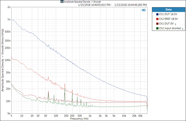
The spikes at 60 Hz and its odd multiples is background EMI; the particular AP515 being used has been through the wringer a few times and is showing its age/could use a refurb & calibration.