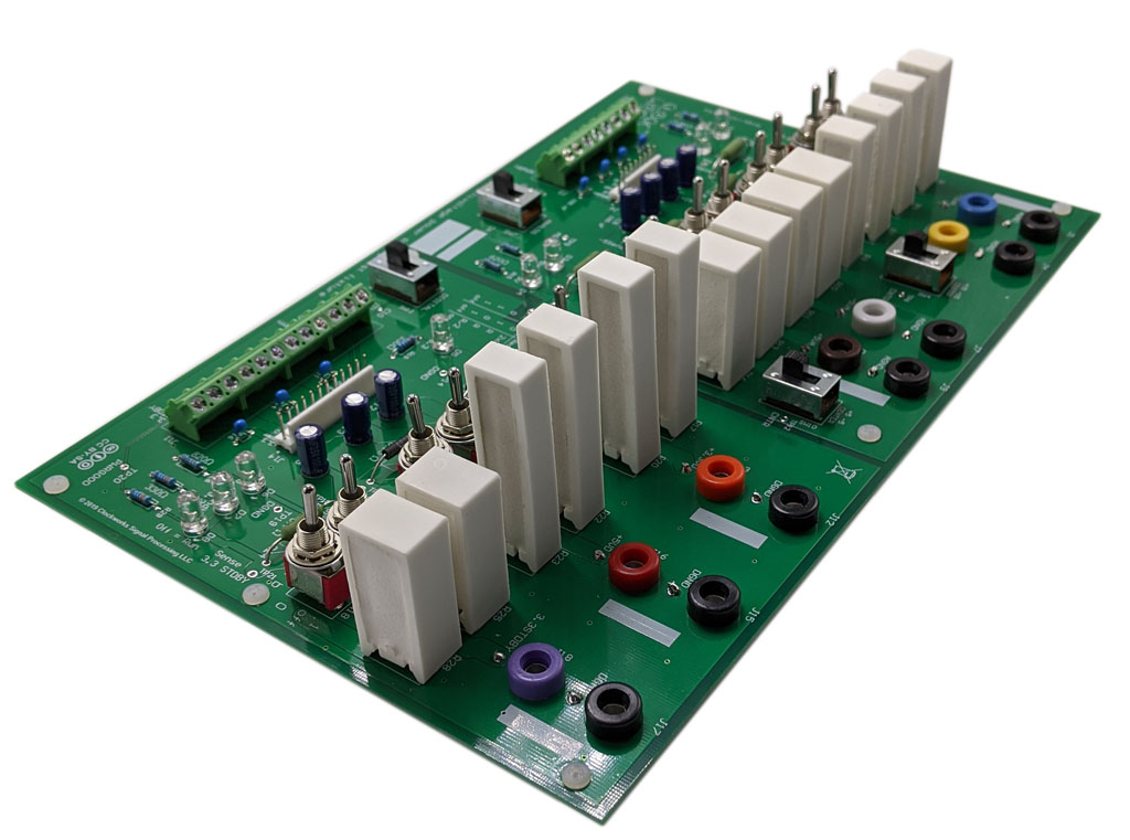
Not a part of the SignalBlox product line, it might be useful to someone else so information about it has been put here. You can purchase the blank PCB or complete kit of parts from our Tindie store.
This board was developed to test the seven and triple output supply under different load conditions to look for noise problems. While using 7 electronic loads could achieve the same thing (actually better since they would be variable loads) it would cost a lot as well as electronic loads were observed to create noise, which is antithetical to trying to determine supply noise. A bunch of resistors and switches will not create unexpected noise.
A PDF of the schematic is available, along with the complete design database. Rev 1 version is what has been posted, changes being made to rev 2 are:
- reduce LED current, they are way too bright
- modify footprint of 10W resistors to allow both 5mm and 7.5mm pin spacing (not all case sizes are actually stocked).
The board has the 8 and 12 pin MTA connectors used by the SignalBlox system, along with screw terminals for use with other systems. It includes switches for the analog and digital supply enables used in SignalBlox systems. LEDs are provided to monitor all voltages along with the power fial signal.
The banana jacks are intended for connecting meters; they are spaced on standard 3/4″ spacing. They could also be used to attach other load values.
Current sense resistors are included on all supplies to verify load currents, a meter can be attached to the sense resistor leads or the test points on the PCB for that purpose.
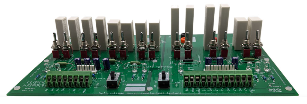
The board includes 100 uF of capacitance on each rail to emulate what a typical load might have. If needed additional capacitance can be placed at the banana jacks.
Two switches determine the load on each supply voltage. If the two resistors are the same value (which is the normal build configuration) then the loads are: open, 2R, R, and R/2. You can use two different resistors to have more load current options. You could also add a load resistor at the banana jacks to create even more possibilities.
The board does not include any cooling, and is sized for 10W resistors; allowing for normal derating figure 5W/resistor. If the load is operated for a short time then the resistor’s thermal mass will work in your favor.
If using the fixture for long term loading tests then a fan is highly recommended.
There’s also a switch for each of the two bipolar supplies to connect the mid point of the resistors to ground. This will also let you load the positive and negative rails differently to see if the supply has problems maintaining regulation with unequal load currents.
For complete details please see the schematic.
PCB blank or a complete kit of parts available from: