
The NA series input connector modules provide a simple way to interface real world analog signals to AnalogBlox and mixed signal DigitalBlox ADC modules.
All input modules offer ESD protection and EMI/RFI filtering. ESD TVS (varistors) are 24V (balanced) and 12V (single ended) max working voltage and rated for 8 kV contact and 15 kV air discharge. Low capacitance devices (< 1 pF typical) to ensure no effect on signal integrity across the audio band.
The effectiveness of the chokes/beads on the input boards will in part depend on the load impedance of the downstream device. Input boards with a RC filter generally use a 100 ohm resistor on the assumption of a high load impedance. The resistor can also serve to limit input current under fault or system no power conditions. Since the input boards can be used with a number of different SignalBlox modules as well as custom user created modules their use must be analyzed at the system level.
There is no resistor to ground, the downstream input should provide a method for keeping analog signals nominally ground referenced (unless a transformer is used).
High quality 0805 metal film resistors and NP0 capacitors are used in the audio path.
The modules are the same size as other SignalBlox modules (75mm x 85mm) but the outside edge has mounting holes that can be used with standard right angle brackets to secure the module to a panel.
All boards are double sided and have ground plane on both sides. Screw and bracket holes are grounded and normal application would dictate that the mounting bracket be grounded to the case and chassis; painted or anodized chassis must have the bracket/standoff mating areas made conductive and if needed, treated to prevent oxidation.
Input (and output) analog modules normally have white silkscreen, which is convenient for marking with a Sharpie when prototyping.
To eliminate cables it’s possible to build cards with sockets instead of headers to allow them to mate to header strips on carrier cards. Other unique arrangements can be built using right angle connectors and/or header strips for connecting boards together without cables nor carrier boards, though the latter use case needs to give consideration to power and control signal connections. If you have unique mechanical needs please contact Clockworks about semi-custom board build options.
 |  |  |
| RCA input | DB25 (balanced/TASCAM) input | Terminal block (balanced with ground per input) |
For XLR or 1/4″ phone input use the appropriate DB25 breakout cable with the NA0101 module, there are multiple options available for this from a wide range of vendors.
NA0100 8 input RCA single ended
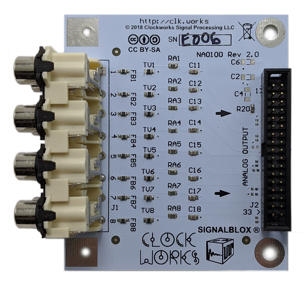
This board provides 8 RCA jacks for single ended input. The “-” output on the 34 pin connector is connected to ground through a pad pair with a cut-able trace.
A ferrite bead (1 Kohm @ 100 MHz) and an RC low pass filter (100 ohm, 100pF, Fc 15 MHz) are provided to protect against high frequency RFI. ESD protection is as described in the summary.
NA0101 25 pin TASCAM style balanced input (for XLR or 1/4″ phone jack input)
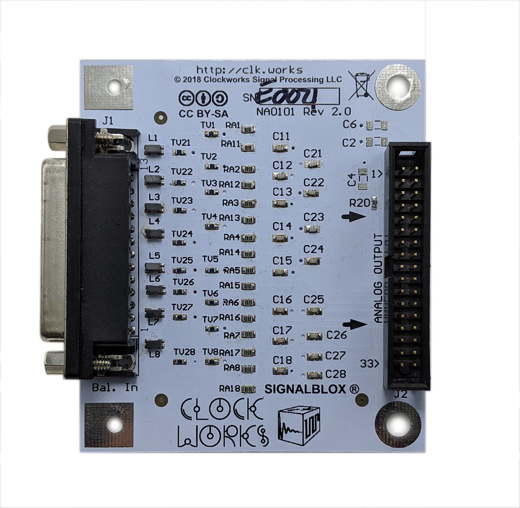
This board provides a TASCAM pinout DB-25 connector. Standard breakout cables can be used to provide eight XLR or 1/4″ phone jacks.
Common mode chokes (1 Kohm @ 100 MHz) and an RC low pass filter (100 ohm, 100pF, Fc 15 MHz) are provided to protect against high frequency RFI. ESD protection is as described in the summary.
NA0109 screw terminal input
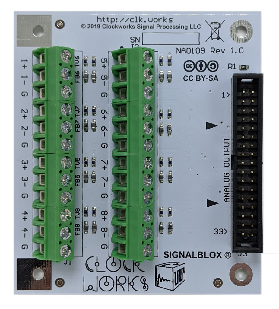
This board provides input for wire termination with high quality Phoenix brand screw terminal blocks (5mm spacing). There are 3 connections for each input, +, -, and ground.
There is no series resistor nor capacitor on the input of this board, it’s just the ferrite bead and TVS.
Coming soon
While we try and not advertise boards that aren’t ready to ship, the following are available in limited quantity as Rev 1 hardware:
RCA input board with jack order flipped
Depending on where the input and output boards are located and/or if mounted upside down, it may be desirable to have pin 1 be on the right side of the board instead of the left. This board is otherwise identical to the NA0100. And of course software can typically reassign usage, but sometimes it’s easier for the hardware to just be what you want.