
The AT series output connector modules provide a simple way to interface AnalogBlox and mixed signal DigitalBlox DAC modules’ outputs. System builder can directly mount these boards in to custom designed cases to create finished systems that look and operate like finished product.
All output modules offer ESD protection and EMI/RFI filtering. ESD diodes are 24V (balanced) and 12V (single ended) max working voltage and rated for 8 kV contact and 15 kV air discharge. Low capacitance devices (< 1 pF typical) to ensure no effect on signal integrity across the audio band.
The effectiveness of the chokes/beads on the output boards will in part depend on the load impedance of the downstream device. Output boards with a RC filter generally use a 50 ohm resistor on the assumption of a mid to high load impedance (1K to 10 K ohm). The resistor can also serve to limit input current under fault conditions. Since the output boards can be used with a number of different SignalBlox modules as well as custom user created modules their use must be analyzed at the system level.
The modules are the same size as other SignalBlox modules (75mm x 85mm) but the outside edge has mounting holes that can be used with standard right angle brackets to secure the module to a panel.
Each module provides 8 balanced outputs, or if supported by the downstream connection and fitted with appropriate connectors, 16 single ended outputs.
All boards are double sided and have ground plane on both sides. Screw and bracket holes are grounded and normal application would dictate that the mounting bracket be grounded to the case and chassis; painted or anodized chassis must have the bracket/standoff mating areas made conductive and if needed, treated to prevent oxidation.
Output (and input) analog modules normally have white silkscreen, which is convenient for marking with a Sharpie when prototyping.
To eliminate cables it’s possible to build cards with sockets instead of headers to allow them to mate to header strips on carrier cards. Other unique arrangements can be built using right angle connectors and/or header strips for connecting boards together without cables nor carrier boards, though the latter use case needs to give consideration to power and control signal connections. If you have special mechanical needs please contact Clockworks about semi-custom board build options.
 |  |  |
| RCA output | Balanced output (DB25 TASCAM) | Terminal block output |
For XLR or 1/4″ phone output use the appropriate DB25 breakout cable with the AT0105 module, there are multiple options available for this from a wide range of vendors.
AT0104 RCA output
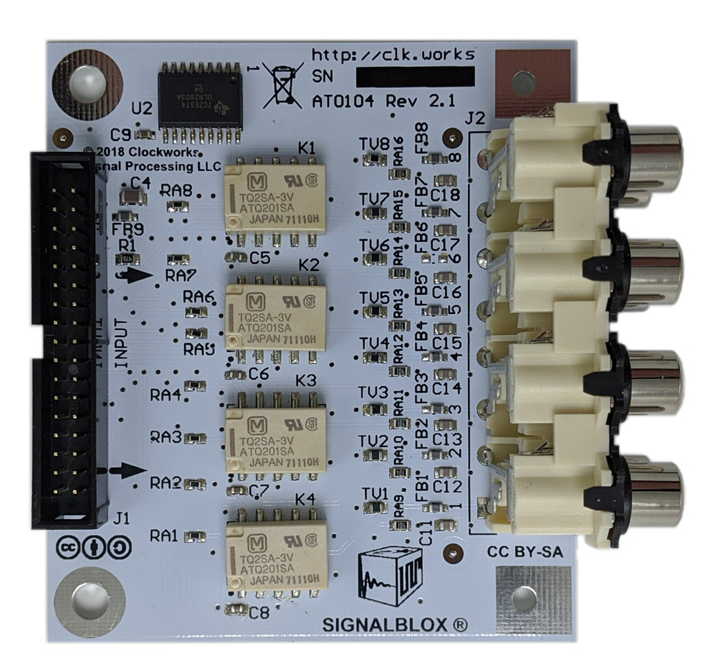
The AT0104 provides 8 RCA jacks for signal output. The input “-” signal is not connected. Muting relays, which would normally be operated under the system host processor control, ensure no clicks and pops during startup and shutdown. A 100K ohm resistor to ground keeps the output ground referenced in the event of AC coupled inputs and the down stream device lacks a ground reference. High quality 0805 metal film resistors and NP0 capacitors are used in the audio path.
The RCA jacks are high quality Switchcraft jacks to ensure long operational life. A 50 ohm series resistor at the input connector is used to limit current from upstream sources that can not directly withstand a short to ground from either a load error or the muting relays being engaged. There is also a small ferrite bead, capacitor, and TVS (varistors) to protect against external RFI and ESD.
AT0105 Balanced out DB25
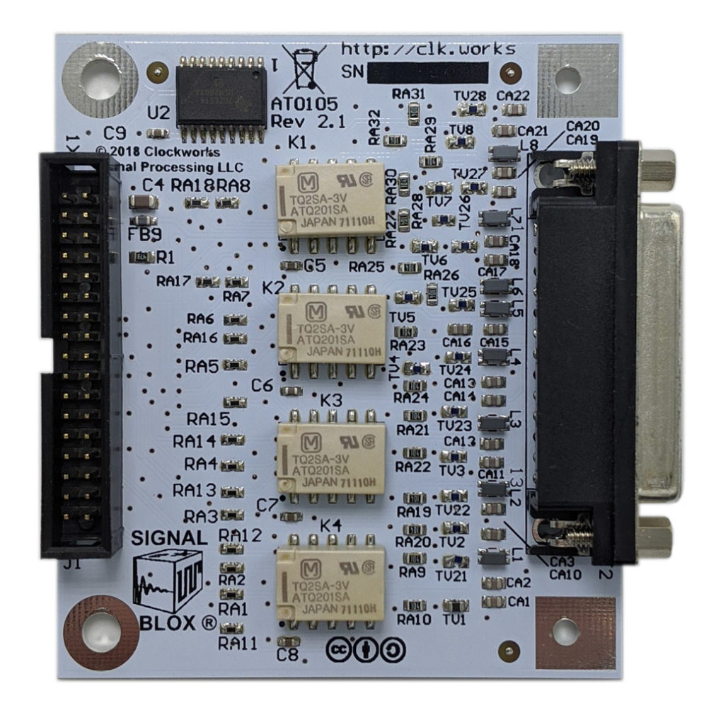
Balanced output from 8 channels is provided by a (female) DB-25 connector that follows TASCAM’s informal standard. (pin 13 is not connected). Muting relays, which would normally be operated under the system host processor control, ensure no clicks and pops during startup and shutdown. The relays short the + and – lines together. A 100K ohm resistor to ground in each leg keeps the output ground referenced in the event of AC coupled inputs and the down stream device lacks a ground reference. High quality 0805 metal film resistors and NP0 capacitors are used in the audio path.
A pair of 50 ohm series resistors at the input connector is used to limit current from upstream sources that can not directly withstand a short to ground from either a load error or the muting relays being engaged. There is also a CM choke, capacitors, and TVS (varistors) to protect against external RFI and ESD.
AT0110 screw terminal output
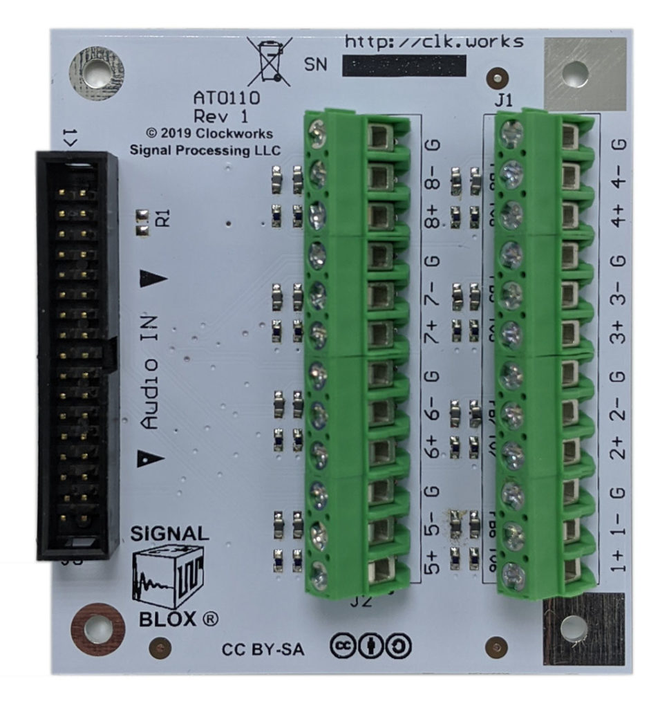
This board provides wire output connections with high quality Phoenix brand screw terminal blocks (5mm spacing). There are 3 connections for each output, +, -, and ground.
A common mode choke is not used on this board as some upstream modules may output 16 single ended signals (by using the + and – lines independently) and this board allows access to those individually. Each line has a small ferrite bead and a TVS (varistors) to protect against external RFI and ESD. There is not series resistor nor resistor and capacitor to ground like on the RCA and DP-25 boards.